HOME PRODUCTS Renewable & Microgrid Static Frequency Converter
-
SERVICES
 NEWS
NEWS  EVENT CALENDOR
  CONTACT US
-
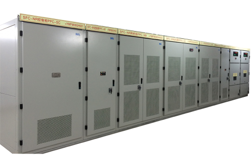
PCS-9575 Static Frequency Converter
The static frequency converter (also named as Load Commutated Inverter, LCI) is a speed governing equipment for providing startup and rotation speed control for large synchronous motor. It can quickly drag the motor to the rotation speed according to the control requirement. Meanwhile, it also can control motor operation at the required rotation speed. It has been widely used in pumped storage power plant, gas turbine power plant and other industrial enterprise.
- Features System Configuration
-
With outstanding performance and extreme reliability, PCS-9575 SFC system adopts a mature power electronics technology aiming the features as:
High reliability and versatility of distributed multi-CPU hardware system.
High resistance to EM interference.
Highly matured visualized modular-programming.
Stable and reliable control of frequency variation.
Complete protection functions of entire system.
Complete fault recording & analysis/external communication functions and friendly man-machine interaction.
Highly integrated control system.
Highly compact and reliable valve design.
Real time phase-lock control generation technique guarantees stable pulses and strong interference immunity.
All kinds of differential protection, over-current protection, and instantaneous protection (di/dt) are being managed by state-of-art protection and control system.
Guarded by forced air cooling for small/medium capacity system whereas closed-loop circulating water cooling (patented technology) for large capacity systems.
Simple and reliable design of heat dissipation system.
PCS-9575 static frequency converter includes primary power equipment and secondary control and protection equipment. The primary equipment consists of input switchgear cabinet, input transformer, rectifier, DC reactor, inverter, output transformer, output switchgear cabinet, SFC output switch, and cooling equipment for converter.
Input Switchgear Cabinet
It consists of input switches/breakers for SFC system.
Input Transformer
By behaving both as a short circuit current suppressor and an isolation node between SFC and power supply, the input transformer also provides the required secondary voltage at the same time. According to the rectifier pulse number and the voltage ratio, 3-winding transformer, 2-winding transformer, step-down transformer or 1:1 isolation transformer can be adopted.
Rectifier
A current source series with reactor adopts 3-phase thyristor full-bridge structure having the options of 6/12-pulsewaves. The thyristor valve bridge arm adopts photoelectric triggering using thyristor control unit (TCU) and highly efficient water/ air cooling for refined and exceeding output.
Reactor
The current source uses a DC reactor for reducing DC current ripple and short circuit current. It is availed with air cooling for optimum performance.However the AC reactors are configured for AC input and output of SFC system in some cases.
Inverter
The Inverter adopts a 3-phase full-bridge thyristor structure with the options of 6/12-pulsewaves. Photo-electric triggering and high efficient water/air cooling make it more efficient for Inversion.
Output Transformer
By making an isolation node between SFC system and motor, output transformer changes the output of SFC to required stator voltage. Depending upon inverter pulse number, the output transformer can be 3-winding transformer, 2-winding transformer, step-down transformer and 1:1 isolation transformer. While in LCI system the output transformer is not configured.
Output Switchgear Cabinet
In SFC system, the output switch cabinet is composed of output switch/breaker and output transformer bypass switch. In case of LCI system, the output transformer with bypass switch cabinet is generally not configured.
Cooling Equipment
Formation of enormous heat during operation may damage the components if it is not dissipated well. During low system capacity, PCS-9575 SFC adopts forced air cooling whereas during large system capacity, it adopts closed-loop water cooling with specialized control system.
Control & Protection System
As the mastermind of PCS-9575 SFC, the Control and Protection System keeps track of every system through acquiring digital and analog data and issues commands for switching/triggering and controlling of analog quantities. The controller analyzes and processes various input signals to perform the monitoring of system operation.