HOME PRODUCTS HVDC & FACTS FACTS
-
SERVICES
 NEWS
NEWS  EVENT CALENDOR
  CONTACT US
-
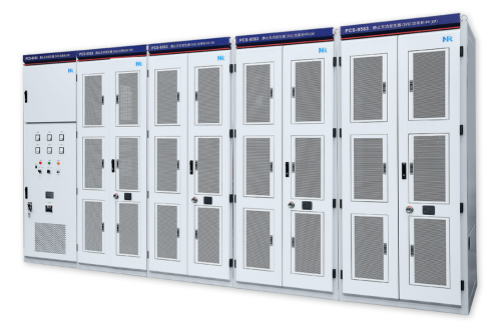
PCS-9583 Static Synchronous Compensator
The Static Synchronous Compensator is a voltage regulating device based on voltage source converters. It acts as a source or a sink of reactive power which is independent of AC system voltage. The STATCOM can adjust reactive power of power grid, improve power quality, and reduce grid losses and the impact on electrical equipment. It is extensively applied to power grid, renewable energy generation, steel mill, chemical plant, electrified railway, city subway, mine and so on.

- Functions System Configuration Operating Principle
-
Power Transmission Substation
Compensate line reactive power and stabilize system voltage
Reduce transmission losses
Increase line transmission capacity through the dynamic support of line terminal voltage
Improve transient stability to prevent against transient voltage collapse
Provide power oscillation damping
Mining Hoists and Industrial Mills
Improve power factor, reduce reactive power loss and energy-saving
Solve serious harmonic pollution problems, and improve power quality by active power filtering
Enhance line terminal voltage, improve voltage stability and power supply security
Reduce voltage fluctuation and flickers caused by heavy load during startup
Electrified Railway
Provide power factor control to reduce power loss
Supply voltage regulation to weak grid
Compensate negative sequence/unbalance current or voltage
Provide harmonic filtering
Wind Farm and Solar Energy
Correct system power factor
Reduce voltage fluctuation and flicker
Filter harmonic current
Balance three phase power
Enhance voltage stability and improve low-voltage ride through (LVRT) capability
Steel Plant and Rolling Mill
Provide harmonic filtering
Compensate unbalanced voltage
Significantly reduce voltage fluctuation and flicker
Improve productivity
Reduce reactive power impact
Control power factor
This complete set of STATCOM system mainly includes the following main equipments:
Interface Reactor/Converter Transformer
The interface reactor/converter transformer is used to connect the converter with the AC power networks, realizing the active power and reactive power exchange between the converter and the AC power networks.
Startup Equipment
To start the STATCOM system, the capacitor at DC side needs to be charged firstly. And for reducing the charging current and the impact on the system, the startup equipment is adopted in STATCOM system.
Power Valve
Power module, as the basic unit of STATCOM system, consists of IGBT and its drive circuit, supporting capacitor, radiator, equalizing resistance and so on. The power valves adopt H-bridge cascaded structure. Each phase consists of a number of power modules, adopting redundant design and satisfying “N-1” or “N-2” operational requirements.
Cooling System
Formation of enormous heat during operation may damage the components if it is not dissipated well. During low system capacity, PCS-9583 STATCOM adopts forced air cooling whereas during large system capacity, it adopts closed-loop water cooling with specialized control system.
STATCOM Control and Protection System
The STATCOM control and protection system consists of PCS-9583 PCP (Pole Control and Protection), PCS-9589 VBC (Valve base Control) unit, SMC (Sub-module controller), interposing relay set, network switch and other protection devices.
PCS-9583 STATCOM system adopts voltage source converter and the most advanced reactive power compensation technology, not needing large-capacity capacitors and inductors. The H-bridge circuit is connected to the grid via connection transformer or reactor, by suitably adjusting the phase angle and amplitude of output voltage at AC side of the bridged circuit or directly controlling its AC current, this circuit can absorb or generate reactive current as required and realize dynamic adjustment of voltage or reactive power.
The cascading scheme of multi-level topology is used in the PCS- 9583 STATCOM system. This topology consists of several H-bridge power units with monopole multiplier modulation to achieve three-level output on the AC side. Each phase adopts the carrier phase modulation method to obtain better voltage output waveform with much more level numbers.The cascading scheme can output phase voltage with 2N +1 levels if each phase comprises N +1 links (i.e. the H-bridge power unit).