HOME PRODUCTS Disturbance Fault Recording
-
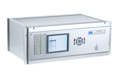
PCS-996R Disturbance Fault Recorder
The PCS-996R disturbance & fault recorder (DFR) is a multifunctional data acquisition system designed to address the data recording requirements of substations. It captures the curves of monitored quantities and aligns the values of different supervised objects to build disturbance records. The PCS-996R helps users simplify disturbance analysis by combining the discrete records in different protective relays.
The disturbance & fault recording system architecture can be centralized or distributed based upon customers’ requests. DFRs can also be applied to a substation independently with a local computer and HMI software. The protocol for the with a local computer and HMI software communication network can be IEC 61850, FTP and IEC 60870- 5-103 based on LAN. GOOSE function is integrated to receive.
Standard format
PCS-996R DFRs are equipped with 48 analog channels and 60
binary channels in one unit. Furthermore, it can be synchronized
via an external time source.
Recording
Triggered recording @ 9600Hz, for short-term transient process.
Continuous recording @1200Hz, for mid-term dynamic process
Slow recording @1 ~ 50Hz , for long-term power quality monitoring
Extract recording @ 9600Hz, isolate fault channels automatically for information efficiency.
- Recording Functions Auxiliary Function Communication
-
Initiating recording by AC voltage Phase voltage over upper limit
Phase voltage under lower limit
Sudden increase/decrease of phase voltage over limit
Negative sequence voltage over upper limit
Zero sequence voltage over upper limit
Sudden change of zero-sequence over limit
Frequency over upper limit
Frequency under lower limit
Absolute value of df/dt over limit
Initiating recording based on AC current out-of-limit Phase current over upper limit
Sudden change of phase current over limit
Negative sequence over upper limit
Zero sequence over upper limit
Sudden change of zero sequence over limit
Power swing
Initiating recording based on binary input
Continuous recording (24hours of uninterrupted recording)
Self diagnostic test
Loss of DC power supply alarm
Hardware circuit online detection
Support IRIG-B time synchronization
1 RJ45 Ethernet port complies with IEC60870-5-103 and IEC61850 protocol
1 RS-485 serial port used for GPS time synchronization
1 RS-232 serial port used to test and configure device
1 Ethernet interface used for FTP service for continuous recording and real-time waveform display
Two fiber Ethernet ports which support IEC60870-5-103 and IEC61850 protocol (available for PCS-996R)